A Guide for Principles of EE I at Rutgers University
September 3, 2015
Introduction
Here we are - a new study guide - for Principles of Electrical Engineering 1 at Rutgers University in the Fall of 2015.
I will try to keep this as up to date as possible as the class goes on throughout the semester. Hopefully addressing all topics in the syllabus. The aim is for this to hopefully be able to serve as a study-guide by the time the end of the semester comes around. I hope that this guide will be able to cover all of the topics that are in this course, as well as provide examples of circuits and step-by-step solutions to different problems.
- Course Instructor: Prof. Hana Godrich
Topics:
- Voltage, Current, Resistance
- Ohm’s Law, Kirkhoff’s Law
- Tools for analyizing circuits
- Node-Voltage Method, Mesh-Current Method -Thevenin and Norton Equivalents, maximum Power Transfer
- Operational amplifiers, inverting, not-inverting and difference amplifier circuits
- Properties of Inductances, etc.
- Review of Complex variables - Intro to sinusoidal steady state analysis, sinusoidal sources, Phasors
- Impedance, Admittance, reactance, susceptance, delta-wye simplifications, Phasor Diagrams
- Sinusoidal steady sate power calculates, RMS values, frequency selective circuits
September 3rd 2015
Definition: Circuit
An interconnection of components or elements that form a closed path or many closed paths.
- For any element or component in a circuit, there are at least two terminals (i.e a connection) on each side of the element
- A node is an intersection of two or more branches or connections off of an element. It can also be thought of as anything that is not part of a component or element.
- Circuits can take many different forms - but they can still perform the same function so long as all of the interconnections are the exact same.
- A Path is a single “way” that you can walk through a circuit. Most circuits will have many, many, many paths. They must be continuous - no breaks in the
- A Branch is a path that moves form one node to another to another. It encompasses only a single element
Basic Circuit Components
- Element or Component: a two - or more - terminal device in a circuit with behavior described by charactieristics which vary with time
- \(V\) or \(v\) - Voltage. Usually talked about voltage drop or gain over an element or component represented with \(+\) or \(-\).
- \(I\) or \(i\) - Current. Current has a direction chosen almost arbitrarily by a person analyzing a circuit.
- Elements and components don’t have to actually be a part of the circuit. For example, we can think of a lightbulb as behaving similarly to a resistor. This means in a circuit diagram we can represent the lightbulb simply as a resistor.
More Definitions
- Essential Node - A node where three or more circuit elements join
- Essential Branch - A path that connects two essential nodes without passing through an essential node. Must include elements in series. (d-g)
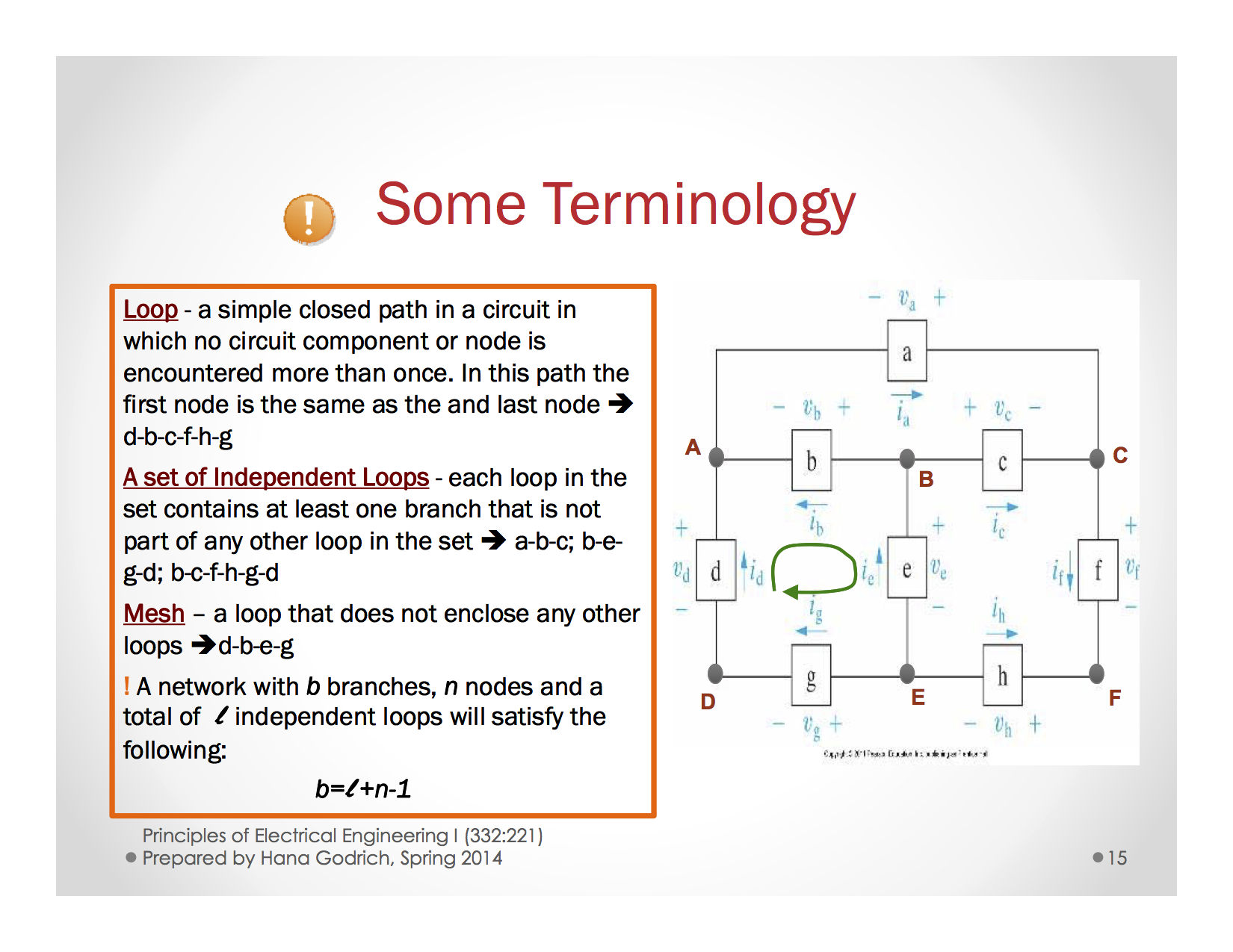
- Loop - a closed path that starts and ends at the same point.
- A set of independent loops - Each loop in the set contains at least one branch that is not part of any other loop in the set(a-b-c, b-e-g-d, b-c-f-h-g-d)
- Mesh - a loop that does not enclose any other loop (d-b-e-g)
- Path - A trace of connecting basic components or sources with no component or source included (a-b-e-h)
- Node A point (junction) within a circuit where two or more circuit elements join. (D)
- A set of Indenpendent Loops - Each loop in the set contains at least one branch that is not part of any other loop in the set
!Important! A network with \(b\) branches, \(n\) nodes and a total of \(l\) indenedent loops will satisfy the following:
\[b = l + n - 1\]
- Note! The above equation also works for the number of essential branches and essential nodes.
See the image below for an explanation
September 6th 2015
Circuit Variables
- Charge: \(q\) or \(Q\)
- Current: \(i\) or \(I\)
- Voltage: \(v\) or \(V\)
- Power: \(p\)
- Energy (or work done): \(w\)
Charge
- Charge is a property that almost all particles posess.
- Like charges repel, and similar charges attract.
- There is a minimum unit of charge is denoted by \(q_e = 1.6 * 10^{-19} C\)
- Measured in Coulombs.
- Coloumb’s law: \(F = k\frac{q_1q_2}{r^2}\)
How does this help us???
Electrical current is actually defined as the flow of positive charge.
It is very important to note that current flow is usually defined as the flow with POSITIVE charge.
Electron Drift
- A conducting wire consists of atoms with loosely attached electrons. The electric force from Coulomb’s law causes the loose electrons to jump from atom to atom inside the metal.
Electrical Current
\[i(t) = \frac{dq(t)}{dt}\]
- The unit Ampere is what we use to measure current - Also defined as Coulomb’s per second.
Voltage or Electric Potential Difference
\[v = \frac{dw}{dq}\]
- The units for voltage is Joules per Coulomb, or \(\frac{J}{C}\)
- Voltage is the energy per unit of charge created by the separation of positive and negative charges
- So we might also say that voltage is the amount of work required to get a certain amount of charge across two terminals.
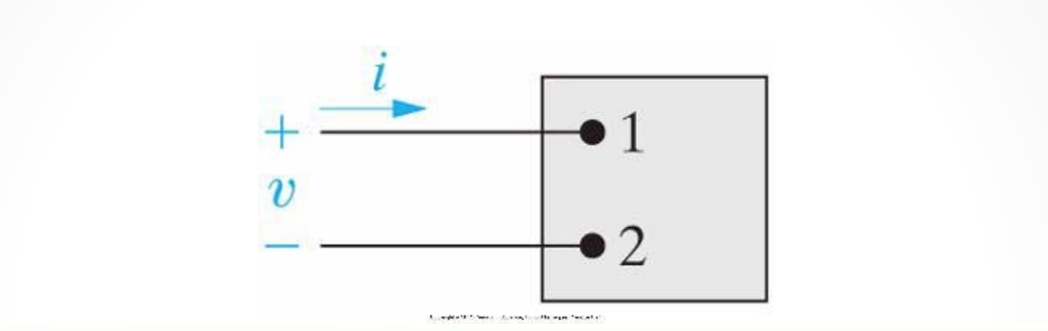
Direction for Current and Voltage
-
When creating circuits, it’s very important to note the direction of current and where voltage drops occur.
- If we see the current directed into the positive terminal and out of the negative terminal, then we see a voltage drop occur.
- If we see current directed into the negative terminal and out of the positive terminal, then we see a voltage gain.
Power
Power, \(p\) is defined as \(\frac{dw}{dt} = iv\)
- Think about multiplying the units of Voltage and Current
- \(\frac{Coulomb}{second} * \frac{Joules}{Coulomb} = \frac{Joules}{second}\) which is the unit for Power.
- In an electric circuit, the total power generated or consumed by elements within the circuit must be equal to 0.
- This means that \(p_{generated} = p_{consumed}\)
- If power is supplied or generated by an element, another element will supplant/cancel out that element’s power out
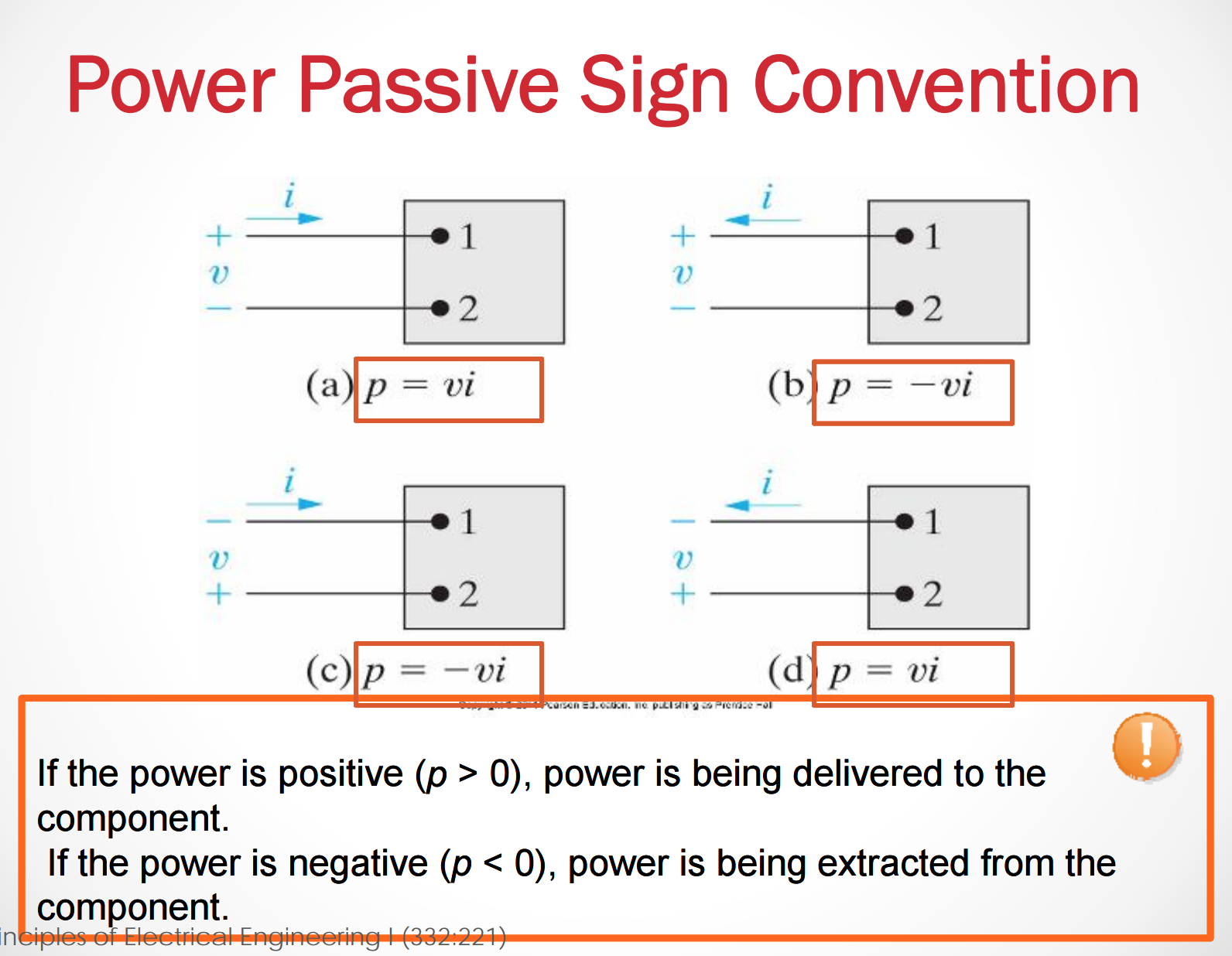
Whenever the current flows in a direction from high potential to low potential (i.e. there is a voltage drop across the element), then the element is consuming the power or energy being delivered to it. (Positive Value
Whenever the current flows in a direction from low potential to high potential (i.e. there is a voltage rise across the element), then the element is generating the power or energy (Negative Value)
- Low potential to high potential: \(p = -iv\)
- High potential to low potential \(p = iv\)
One way to think of it - is that whichever terminal (positive or negative) the current is flowing into - that is the going to be the sign of the power equation.
Example:
- Current flows into the positive terminal of an element in the circuit –> \(p = iv\)
- Current flows into the negative terminal of an element in the circuit –> \(p = -iv\).
See below for more explanation
Passive Sign Convention
Finding the power consumed or delivered by an Element
If we have multiple elements in a circuit, we know the voltage drop/rise across each, and the current for all but one element, then we can find the power that is being delivered across the final element. We follow just a few simple steps
- For each element, find if the power is consumed or delivered.
- For each element calculate the power the is being consumed or delivered.
- Add all of the power across each element up. Whatever the remaining difference is, the opposite sign (positive/negative) is the amount of power delivered across the last element.
September 10th 2015
Unit 2 Circuit Components
Topics covered in this Unit:
- Inpedendent Source
- Depedent Source
- Passive Circuit Elements
- Resistance and Ohm’s Law
- Kirchoff’s Law
- Sources Interconnection
- Components Interconnection
- Circuit Modeling and Circuit Analysis
Circuit Components Symbols: Ideal, Independent, Voltage Source
Independent Voltage Source: Generates a voltage drop across its terminals without relying on other voltages in the circuit.
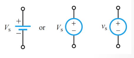
- Independent sources are always marked with a circle
An ideal voltage source supplies the same voltage regardless of current.
Independent Current Source: Generates a current through a branch in a circuit without relying on other currents in the circuit.
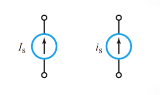
An ideal current source supplies the same current regardless of voltage.
- It is very important to note here that the two sources we just introduced do not effect the other properties of the circuit. i.e. the independent voltage source will not change anythign about the current, and the independent current source will not change anything about the voltage.
DC (Direct Current) & AC (Alternating Current) Sources
There are two types current sources that are present in electric current. AC (Alternating current), and DC (direct current). In the images below you can see the difference in these two types of currents.
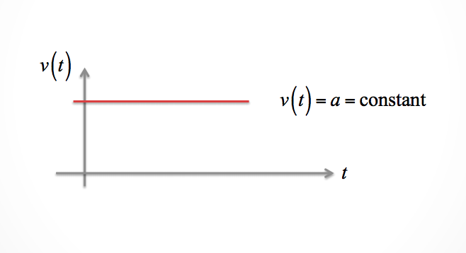
Direct Current
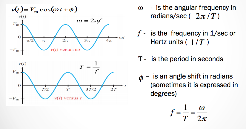
Alternating Current
- AC in the United States changes at a frequency at 60Hz. Many other countries in the world use 50Hz.
- AC is usually used to transmit power to power plants and so on.
- See chapter 9 for advantages and disadvantages of AC and DC current.
Additional Circuit Sources
Dependent Sources Generate a voltage whose value depends on the value of another voltage or current in the circuit. They are usually represented by a diamond.
Voltage Controlled Voltage Source (VCVS): \(v_s = \alpha v_x\) Current Controlled Voltage Source (CCVS): \(v_s = ri_x\)
- Note: \(\alpha\) and \(r\) are constants
- \(v_x\) and \(i_x\) are a specific voltage and a specific current elsewhere in the circuit.
Voltage Controlled Current Source (VCCS): \(i_s = gv_x\) Current Controlled Current Source (CCCS): \(v_s = \beta i_x\)
- Note: \(g\) and \(\beta\) are constants
- \(v_x\) and \(i_x\) are a specific voltage and a specific current elsewhere in the circuit.
Interconnection of Sources
Voltage Sources
Voltage sources in parallel must be of the same value.
- A good analogy for voltages changes is that it is a change in elevation. Think of walking up a mountain. If you walk up a mountain 10 meters. Then you walk down 10 meters. You end up at the same elevation.
-
Now think of walking up and down the mountain as the change in voltage level instead. Where elevation is the same as voltage change.
- Voltage sources of any type can be connected in series. It will step up (or down) the voltage whatever the direction.
- Voltage sources in parallel must be of the same value.
Current Sources
Current sources connected in series must be of the same value.
- Current sources connected in parallel are okay. Current flow on the sources essential branch can be maintained without interference.
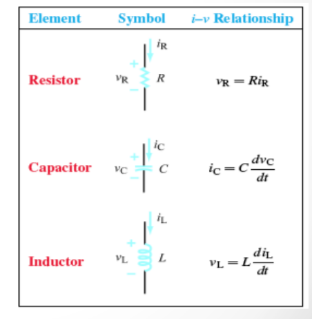
Passive Circuit Components Symbols
Passive Circuit Component: A device that cannot generate electric energy and does not require external power sources to operate.
There are three types of passive circuit components:
- Resistors
Equation: \(v_R = Ri_R\)
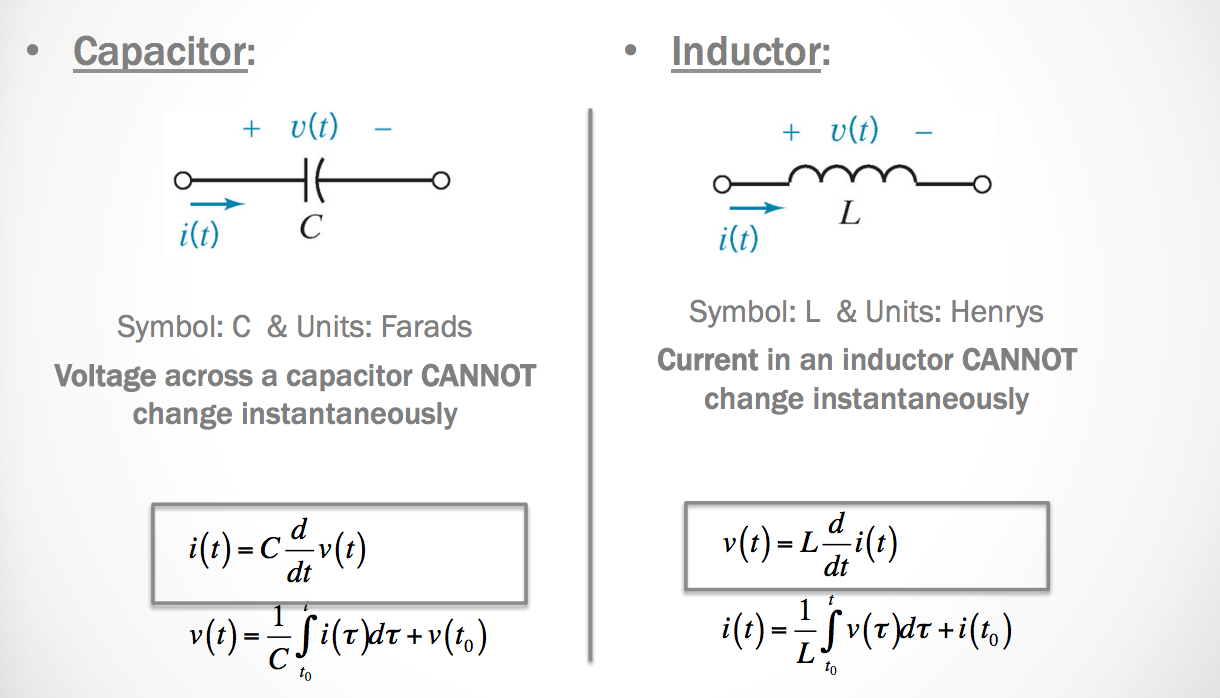
- Capacitor:
Equation: \(i_C = C\frac{dv_C}{dt}\)
- Inductor:
Equation: \(v_L = L\frac{di_L}{dt}\)
Resistance
Resistance: The physical property of an element that impedes the flow of current (electron drift)
Represented by \(R\) and is defined by:
- \(\rho =\) resistivity in \(ohm\cdot cm\)
- \(l =\) length of material in \(cm\)
- \(A =\) cross section of the material in \(cm^2\)
\[R = \frac{\rho \cdot l}{A}\]
The unit of resistance is the Ohm –> \(\Omega\)
Ohm’s Law: Linear Model
\(v= i \cdot R\) or \(i = \frac{v}{R}\)
When the voltage is positive and current flows into the positive terminal, then the current drops.
The voltage, \(v\) across and the current, \(i\) through a resistance \(R\) that flows down the potential hill
Power delivered to a resistor: \(p = i^2R=\frac{v^2}{R}\)
Note! Power is always consumed by a resistor (positive).
Hold up! hold up! I just said that power consumed by a resistor is always positive. How is that possible? What if we switch the positive and negative terminals?
Resistors don’t actually have positive and negative terminals. You can just assume - no matter the orientation or current flow - that they will be consuming power.
September 14 2015
Unit 2, Lecture 2
Calculating Power From Ohm’s Law
We know now that \(p = iv\), right? We also know that from Ohm’s law, \(v = iR\). This can then give us a new equation to calculate power based on resistance.
- \[p = iv = i \cdot (iR) = i^2R\]
Another form is:
- \[p = iv = (\frac{v}{R}) \cdot v = \frac{v^2}{R}\]
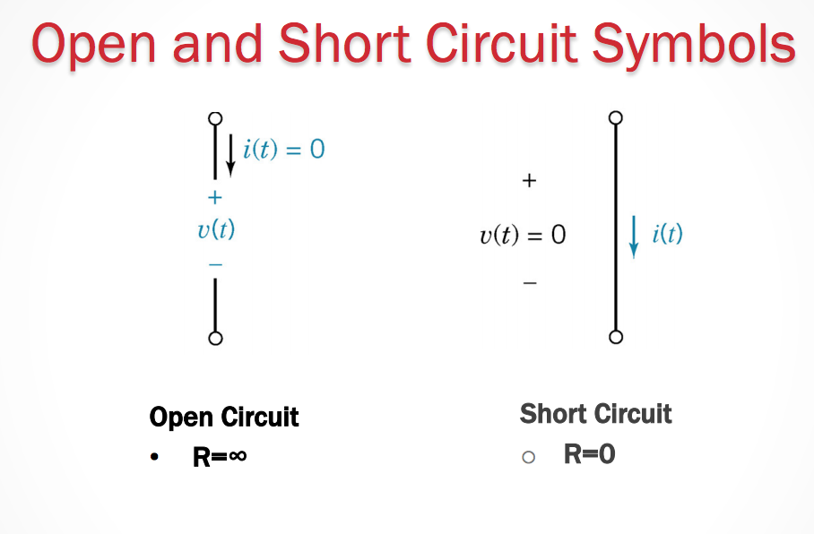
Open and Short Circuit Symbols
- In a short circuit the Resistance through between two nodes is 0.
- In a closed circuit the resistance between two nodes is \(\infty\).
The Switch Symbol
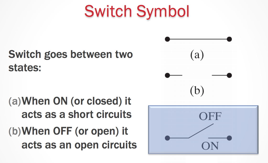
- Switches can affect the direction the current will flow.
- The current will try to take the path of least resistace.
If a current can take a path through a circuit that eliminates flow through a resistor, then the current will not flow through to that part of the circuit (or resistor) at all.
Kirchoff’s Laws
Arguably some of the most important equations in solving circuits come from Kirchoff’s laws. They help us gain information about a circuit to be able to obtain and solve for different component’s quantities.
Let’s start off with current, \(i\).
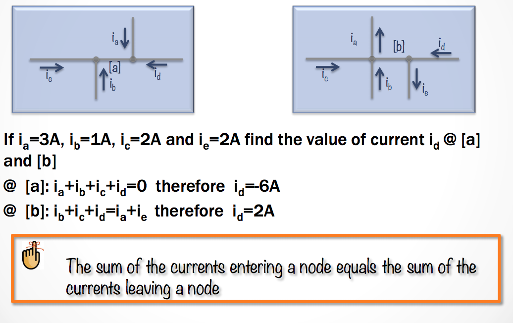
Kirchoff’s Current Law
The algebraic sum of all the currents at any node in a circuit equals zero.
What does this mean?
- We can pick any nodes in our circuit. A node should always have at least two currents flowing into it. This means that those two (or more) currents flowing into that node must sum to equal 0.
\[\Sigma_j i_j = 0\]
- We ADD currents entering a node. (Postive)
- We SUBTRACT currents leaving a node. (Negative)
Now! We are going to see a similar law, but this time it will apply to voltage.
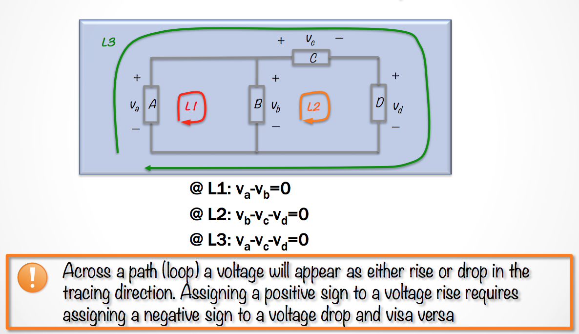
Kirchoff’s Voltage Law
The algebraic sum of all the voltages around any closed path in a circuit equals zero.
So what exactly does this mean? It means that we can pick any closed loop in the circuit. When we follow that loop we must add (or subtract) the voltages over different elements together to give us a final sum of zero.
- If the element causes a voltage drop (positive -> negative), then we subtract.
- If the element causes a voltage rise (negative -> postitive), then we add.
\[\Sigma_j v_j = 0\]
- Here’s one more example problem you can use to test your calculation skills.
Mastering these problems takes lots of practice - so it could be beneficial to find more problems online or in a textbook to practice calculating and solving for circuits.
September 21st 2015
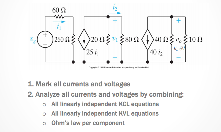
How many KCL and KVL Independent Equations?
- KVL
\(b-n+1\) independent loop equations OR \(b_e - n_e + 1\) Is the number of essential branches and \(n_e\) is the number of essential nodes
- KCL
\(n - 1\) independent node equations OR \(n_e - 1\) if every essential branch has a single current associated with it.
Steps to Solve for a Circuit
-
Mark all nodes, resistors, currents, and voltages including direction and polarity.
-
Choose Nodes for KCL
-
Choose Loops for KVL
-
Write KCL equations –> \(n_e - 1 = 3\)
Unit 3 - Simple Resistive Circuits
In this unit we’ll address creating circuits that contain resistors in series and parallel - and then finding methods for learning about how to simplify said circuits and then solve for them.
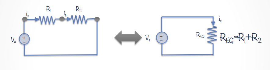
Resistors In Series
Resistors are an element within a circuit - and sometimes these elements are difficult to solve for indicidually. But what we can do is simplify these circuits with multiple of similar elements to make solving these circuits easier.
Resistors in series mean that the resistors are in a “line” with each other. There are no essential nodes between the two resistors. In this case (where there are no essential nodes) we can simply add the resistances of each resistor together
\[R_{eq} = R_1 + R_2\]
From here on our circuit diagrams we can simply just combine the two resistors into one, where the single resistor now has the resistance of \(R_{eq}\).
September 24th 2015
Simplifying Circuits with Resistors in Series and Parallel
Resistors in Series
We can simplify resistors that share a single essential node. We know that they are in series if they share an essential node and there are no other elements in between them. We can simply add their resistances.
So for resistors in series
\[R_{eq} = R_1 + R_2\]
Some notes about simplifying resistors in series
- The current through both resistors is the same. You can prove it using KCL.
- The voltage drop is related to the addition of the voltage drop across each individual resistor.
Resistors In Parallel
Resistors in parallel is where two resistors share a node with another branch from an element. To find the equivalent resistance we must use the reciprocal of the resistances.
So for resistors in parallel:
\[\frac{1}{R_{eq}} = \frac{1}{R_1} + \frac{1}{R_2}\]
Therefore
\[R_{eq} = \frac{R_1R_2}{R_1 + R_2}\]
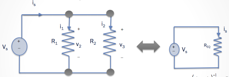
The equivalent resitance of resistors in parallel will ALWAYS be smaller than the minimum resistance in the set of parallel resistors.
The Delta-Wye Connection
In the triangular (Delta) configuration - We name the resistors in a very systematic way.
- For the branch between node a and b, the resistor must be \(R_c\).
- For the branch connecting nodes b and c, the resistor must be \(R_a\).
- For the branch ocnnection nodes a and c, the resistfor must be \(R_b\).
In the Wye (Y) configuration
- The (a) node should be connected to \(R_1\).
- The (b) node should be connected to \(R_2\).
- The (c) node should be connected to \(R_3\).
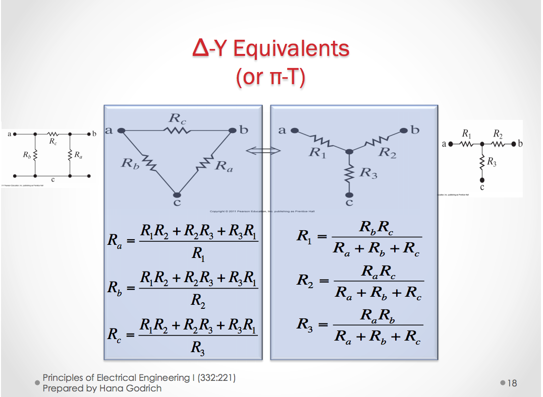
This transformation to and from the Delta and Wye (Y) configurations can be useful in analyzing more complex circuits.
September 28th 2015
Voltage Divider Circuit
So the first thing we need to know is that if we want to measure the voltage over a resistor, then we need to put the voltmeter in parallel with the resistor.
Now in a voltage divider circuit, we take that principle and expand on it to divide the voltage by a certain amount by putting multiple resistors in series with one another.
The voltage divider contains a voltage source of value \(V_x\) and resistors \(R_1\) and \(R_2\) in series with one another and the voltage source.
We know that from KVL the equation for the voltage must be that
\[V_x = V_1 + V_2\]
From KCL we can find that
\[i_x = i_1 = i_2\]
and now from KCL and Ohm’s we have
\[i_x = \frac{V_1}{R_1} = \frac{V_2}{R_2}\]
we want to now find \(V_1\) in terms of \(V_x\).
- \[V_1 = f(V_x)\]
- \[V_2 = f(V_x)\]
We can then find that \(V_x = V_1 + \frac{R_2}{R_1}V_1 = (1 + \frac{R_2}{R_1})V_1\)
So then solving for \(V_1\) we find:
\[V_1 = \frac{R_1}{R_1 + R_2}V_x\]
Similarly, if we solve for \(V_2\), then
\[V_2 = \frac{R_2}{R_1 + R_2}V_x\]
Current Divider Circuits
In a current divider circuit we can divide a voltage source’s current by an amount by placing resistors in parallel and putting an ammeter in series with one of the resistors.
So if we have two resistors in series, then through KVL we have:
\[V_x = V_1 = V_2\]
and through KCL we have that
\[i_x = i_1 + i_2\]
And with Ohm’s law included, we can get the equation
\[i_1 = \frac{R_2}{R_1 + R_2} i_x\]
So then if we solve for \(i_2\) we find that
\[i_2 = \frac{}{}i_x\]
October 1st 2015
The Wheatstone Bridge
In a Wheatstone bridge, the \(R_x\), (resistor with unkown resistance) is equal to:
- \(R_x = \frac{R_2R_3}{R_1}\). Where \(R_2\) and \(R_3\) are the resistors that shore a branch with \(R_x\).
Unit 4a Node-Voltage, Mesh-Currnet, & Source Transformation
The Node-Voltage Method
In the node voltage method, you must pick a node as a reference node. At that node we say that it is \(V_g = 0 V\). From here we can create equations that represent the voltage drops over multiple elements.
You can add the voltage drops over multiple elements to remove the amount of variables involved in the cicuit. From here we can represent each element with a difference between two different node voltages.
We can now convert some of these node voltages into current equations. The equation for current between two nodes with a resistance R is equal to:
\[i = \frac{V_b - V_a}{R}\]
Note that the value \(V_a\) is the value of the node connected to the resistor on one end, while \(V_b\) is equal to the voltage of the node at the other. \(V_b - V_a\) represents the voltage drop across the resistor.
The steps for Vode-Voltage Analysis:
- Mark all nodes, node voltages, and choose a reference (ground) node.
- Write the node voltage equations
- Calculate node voltages, elements, and current voltages.
October 5th 2015
Reviewing Node-Voltage Analysis
For every essential node we assign it a voltage V.
In essence, the nodal-voltage analysis is directly related to kirchoff’s current law. We calculate the voltages by the adding the currents that end up in each essential node.
The equations usually end up in a formal similar to the following:
- \[0 = \frac{V_A - V_B}{R} + \frac{V_A - V_C}{R}\]
If a voltage source is the only element between two essential nodes where one of the nodes is the reference node, the number of unknown node voltages is reduced.
- If a resistor is in series with a current source, the resistor will not change the amount of current flowing through the resistor. So this means it does not change the KCL equation for the nodal analysis.
Constraint Equations
A constraint equation is an equation in our node voltage (or mesh current) analysis where based on a current source or voltage source that determines when a specified potential difference MUST be a specific value between two nodes due to one of these sources.
Supernodes
When a voltage source is between two essential nodes (other than the reference node) we can combine those to form a supernode.
The Mesh Current Method
The mesh current method mimics the node-voltage method in the idea that it is based off of one of Kirchoff’s laws. In this case, it is based off of Kirchoff’s voltage law (KVL).
- Remember that a mesh is a loop that does not contain any other loops in a circuit.
In the mesh current method we assume that we always hit resistors in the positive terminal. But when we hit others, we assume that if we hit the negative terminal, it will be negative, and positive terminal, positive.
-
When two different loops share a resistor, we take the difference (or sum!) of the currents depending on the direction of the loops.
- If the directions are the same, we add currents from each loop, i.e. \((I_A + I_B)R\).
- If the directions are opposite of each other, we take the difference. i.e \((I_A - I_B)R\).
October 15th 2015
Current Sources: Shared by two mesh currents
Supermeshes
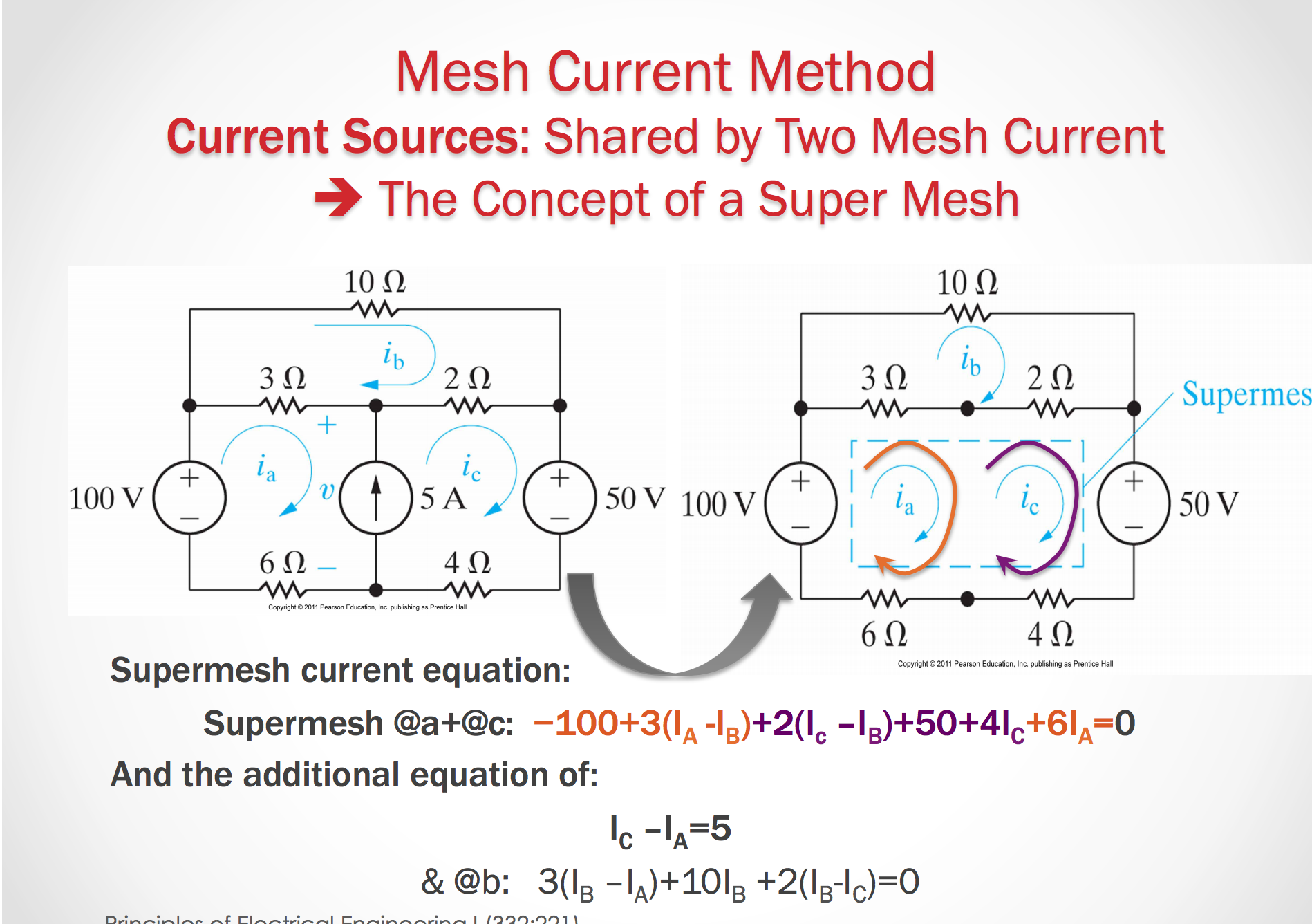
Some notes on a Super Mesh
Case 1:
- Sum (all meshes) = Mesh A + Mesh B; while skipping all elements on the branch that contains the current source
- In each mesh, the local mesh current is used!
Case 2:
- Sum (all meshes) - SUM(all meshes in other direction) = Mesh A - Mesh B; while skipping all elements on the branch that contains the current source
- In each mesh the local mesh current is used.
Node Voltage or Mesh Current?
Deciding which approach to take in a particular circuit usually boils down to determining which method leads to easier math - the fewest numer of simultaneous equations
-
Evaluate the number of equations for node-boltage and the mesh-current method that results in the smallest number of equations
-
Networks that contain many series connected elements, voltage source or super meshes are more suitable for mesh analysis.
-
Network with parallel connected elements, current sources, or supernodes are more suitable for nodal analysis.
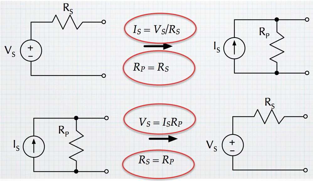
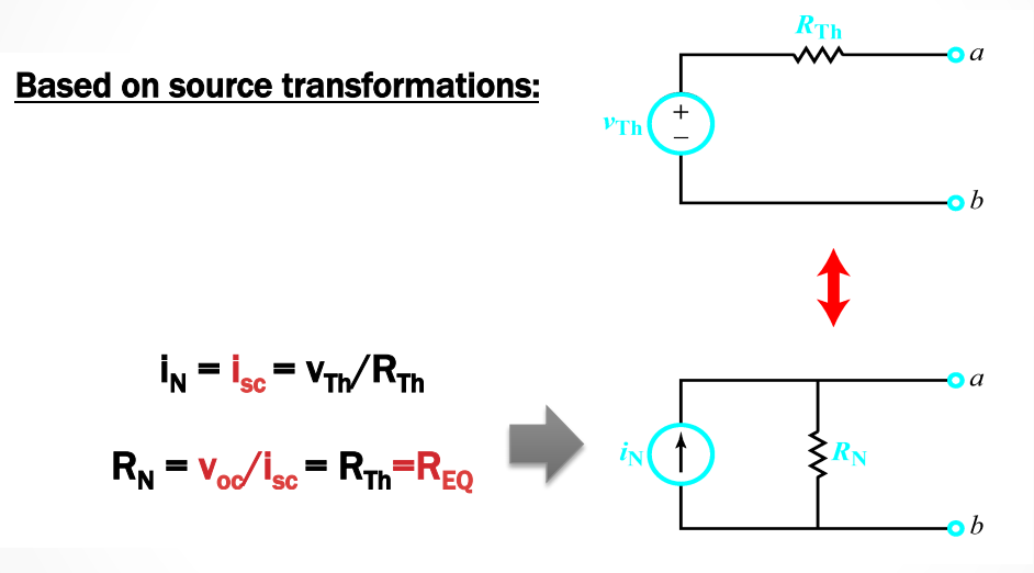
Source Transformations
How can we change a voltage source or current source, with its opposite type, while still keeping the original behavior of the circuit?
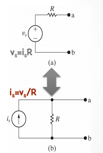
We want to keep the same behavior of the circuit, so we must use equivalent resistance and collapse parts of the circuit to transform the sources. We need to make sure that current and voltage are preserved.
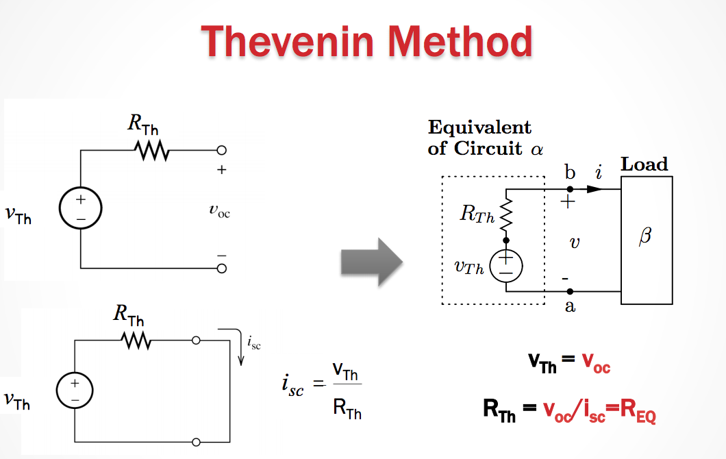
Thevenin Equivalent
Suppose we have a section of a circuit name \(\alpha\). This \(\alpha\) is connected to another section \(\beta\). Now \(\alpha\) is a part that we always know will be constant. But what if \(\beta\) can change? How can we represent \(\alpha\) to simplify our calculations with different loads, \(\beta\)?
Thevenin Theorem
If \(\alpha\) is a linear circuit with passive or active elements, with all controlled and controlling branches contained within \(\alpha\), then we can replace entire network \(\alpha\) by an equivalent circuit that contains one independent voltage source in series with a single resistor (impedance) in series with it, such that the current-voltage relationship at \(\beta\) is unchanged.
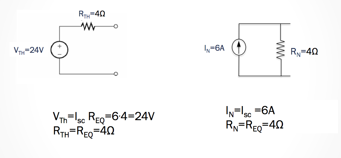
Norton Equivalent -> A source transformation on Thevenin
Norton’s Theorem
Identical to thevenin theorem only that the equivalent circuit is one independent current source in parallel with a single resistor (impedance)
- The Norton equivalent circuit is a source transformation of the Thevenin equivalent circuit.
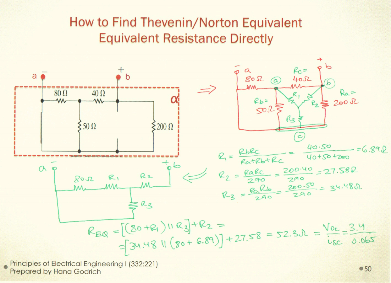
How to Find the Thevenin/Norton Equivalent
- Remove all elements that do not belong to th \(\alpha\) circuit - Usually refers to removing the output load
- Do TWO of the following
- At the \(\alpha\) circuit, at the output terminals a-b, calculate the short-circuit current
- At the \(\alpha\) circuit at the output terminals a-b calculate the equivalent resistance \(R_{eq}\) as seen by the output. i.e. as if we have a voltage source connected between terminals a and b and \(R_{eq} = \frac{V_{in}}{I_{in}}\)
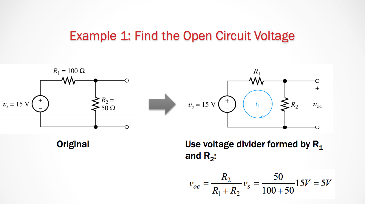
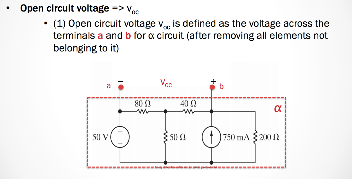
- For the \(\alpha\) circuit, find the \(V_oc\) over the circuit where the split between terminals a and b is an open circuit.
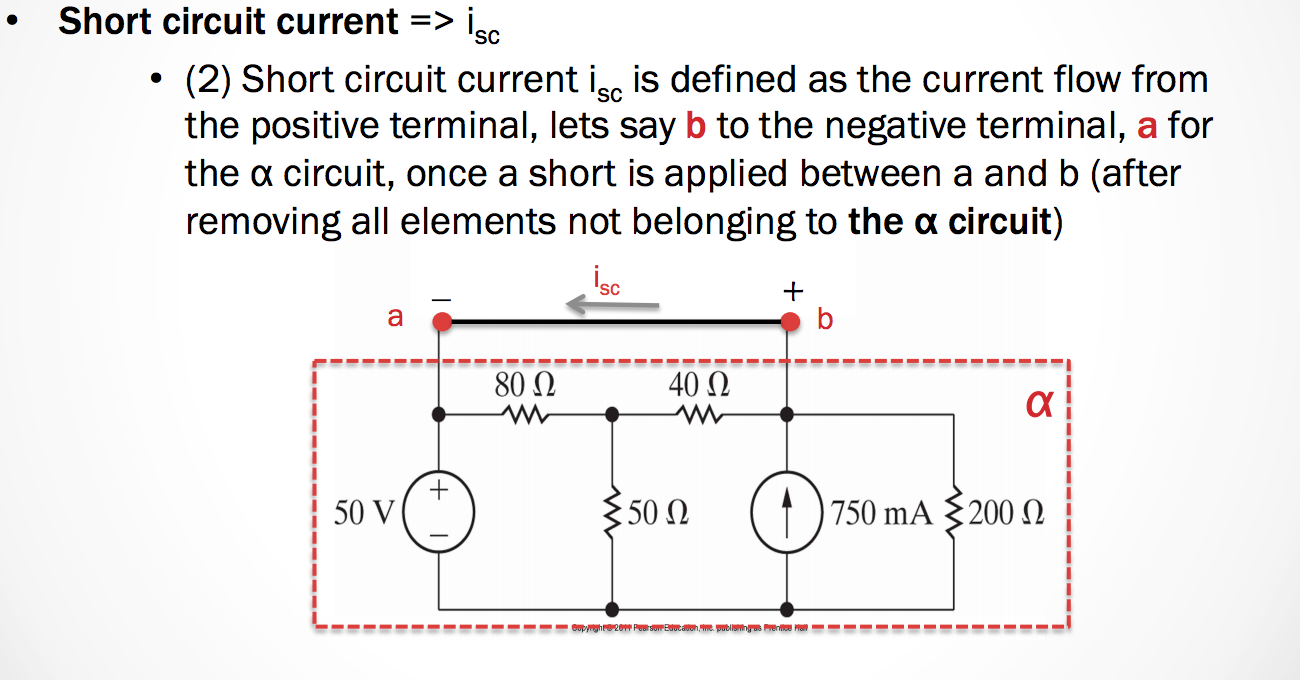
-The short circuit current is calculated by making a short between terminals a and b, and finding the current flowing through this short from the positive terminal to the negative one.
- Notice that the voltage drop between terminals a and b should be zero.
- The short circuit current \(i_{sc}\) is defined as the current flow from the positive terminal, lets say, b, to the negative terminal, a, for the \(\alpha\) cicuit, once a short is appllied between a and b (after removing all elements not belonging to the \(\alpha\) circuit)
Caution!
- The Thevenin and Norton equivalents can be used only when the circuit \(\alpha\) does not have any controlling variables that control some dependent source which is the circuit \(\beta\).
- Access to the controlling variable and therefore to the knowledge of how to characterize the dependent source which is in the circuit \(\beta\) is lost.
October 19th 2015
Thevenin and Norton Equivalents with Independent Sources
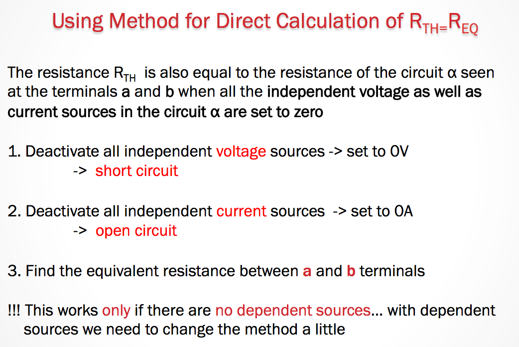
Method for direct calculation of \(R_{TH}=R_{EQ}\).
- Deactivate all independent voltage sources –> Set them equal to \(0V\).
- Short Circuit.
- Deactivate all independent current sources –> Set to\(0A\).
- Find the equivalent resistance between the \(a\) and \(b\) terminals
(This only works if there are no dependent sources.)
However, we can modify this method slightly so that it is possible to calculate the \(R_{TH}\) even if there are dependent sources.
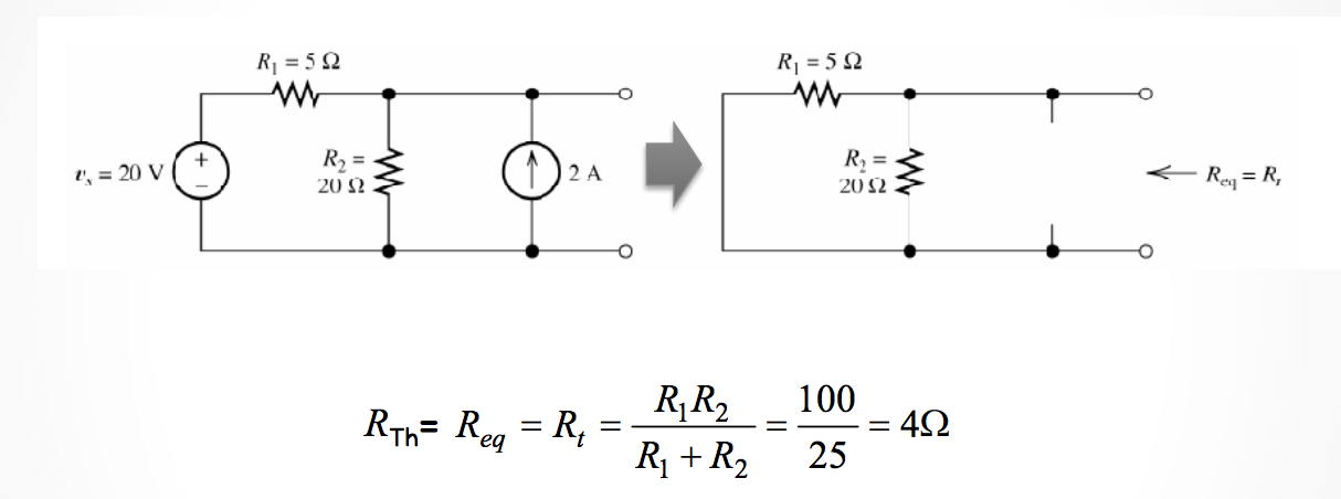
So after we calculate our equivalent resistance. We then need to find the voltage drop (or total current) through that branch of the circuit.
After finding the current through it, then we can replace the entire circuit (up to the terminals) with our thevenin or Norton equivalents.
Thevenin and Norton Equivalents with Dependent Sources
Okay, so now we know how to calculate the Thevenin and Norton Equivalents, but what if there are dependent sources?
We need to do the following:
- Deactivate all independent voltage sources –> Set to \(0V\).
- Deactivate all independent current source –> set to \(0A\).
- Add a test source, \(V_T\), between the terminals \(a\) and \(b\).
- The Thevenin resistance is then \(R_{TH} = \frac{V_T}{i_T}\).
For example, if we find \(V_T = 1V\), then we just need to find the \(i_T\) from \(R_{TH} = \frac{1}{i_T}\).
While this method does introduce an extra variable, it still makes it relatively easy to calculate the equivalents with the node-voltage or mesh-current methods.
Notes on Supermeshes
Case 1 All mesh currents in a super mesh follow the same directions:
- In a supermesh, then we need to add the equations. so we have SUM[all meshes] = (Mesh A) + (Mesh B) – while skipping all elements that contain current sources.
- In each mesh, the local mesh current should be used.
Case 2 Not all mesh current in a super mesh follow the same direction:
- Sum[al meshes in one direction] = (Mesh A) - (Mesh B) – while skipping all elements on the branch that contains the current source.
- In each mesh the local mesh current is used!
Maximum Power Transfer
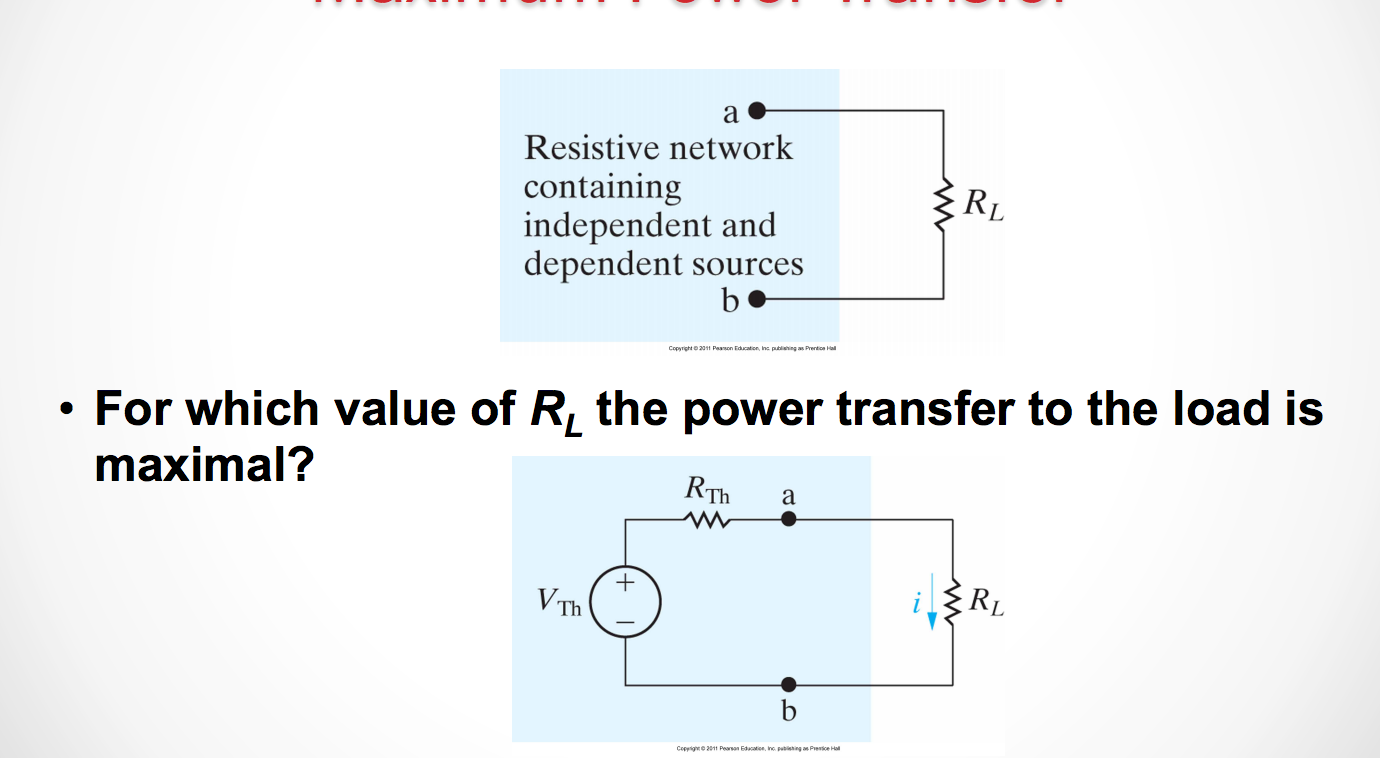
To find the maximum power, we need to take the derivative of the power and find the poitn where the derivative equals 0, because that will maximize (or minimize) the value for power.
So if we take the equation \(P = i^2(R_TH + R_L)\) or \(P = \frac{v^2R_L}{(R_{TH} + R_L)^2}\).
Now if we take the derivative with respect to \(R_L\), then we find that:
\[\frac{dP}{dR_L} = [\frac{v^2R_L}{(R_{TH} + R_L)^2}] = 0\]
So then from there we can find the P_{max} is when \(R_L = R_{TH}\).
Then our \(P_{max} = \frac{V^2_TH}{4R_L}\)
Finding the Thevenin/Norton Equivalents for a larger Circuit.
See The following problem to see how to calculate the Thevenin equivalent for a whole circuit
October 22nd 2015
The Superposition Principle
- In a ciecui with independent voltage sources we can find a current through an element or voltage across an element as the sum of the contribution of individual sources in the circuit.
How?
- At each stage, set all sources except for one equal to zero and find the contribution of this individual source to the current through an element or voltage across an element
- The total current through an element or voltage across an element is the sum of all individual contributions
REMEMBER:
- Setting a voltage source to zero means making it a short circuit.
- Setting a current source ot zero means making it an open circuit.
At each stage, set ALL sources ecept for ONE to zero and find the contribution of this indicidual source to the current through an element or voltage across an element
- The total current through an element or voltage across an element is the SUM of all individual contributions.
Operational Amplifiers
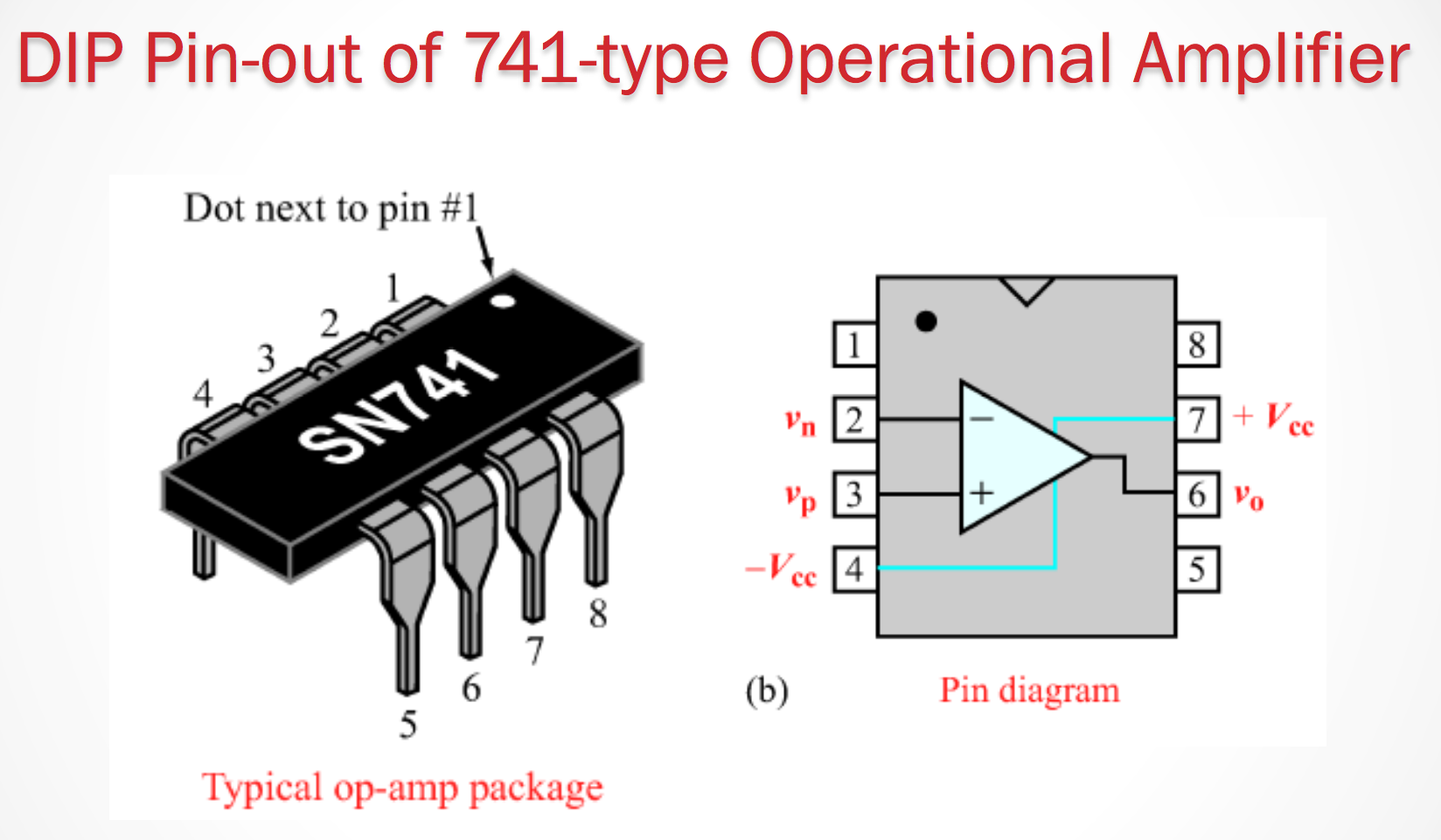
For our purposes, operational Amplifiers are a 5 terminal element.
There are 5 terminals:
- Noninverting input
- Inverting input
- Positive power supply
- Negative power supply
- Output
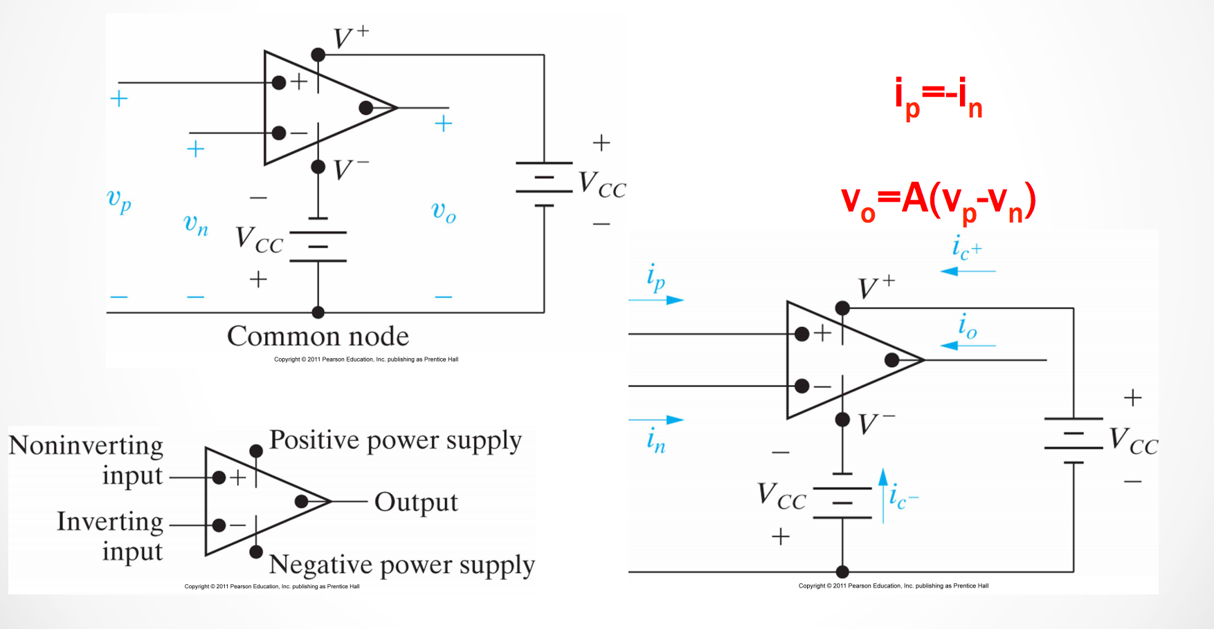
An operational amplifier amplifies the difference between the inverting input and the non-inververting input.
We can simplify the behavior for an op. amp. so long as the voltage remains in the linear region of the amplifier’s operation. This allows us to simpligy the model.
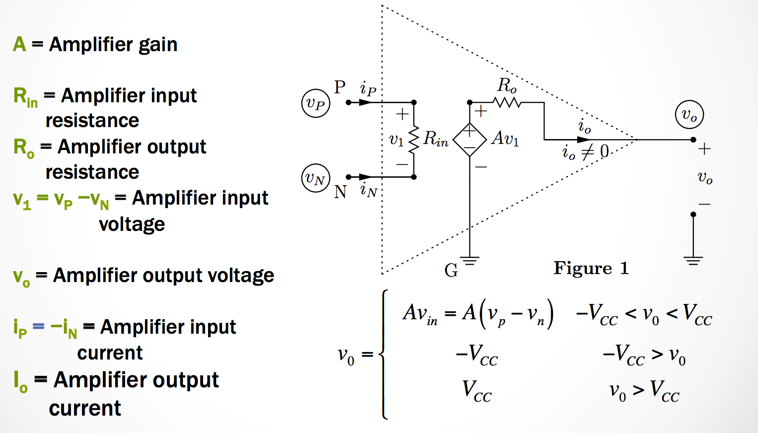
A good Op-Amp circuit model has 3 important characteristics
- Op_Amp gain, \(S\) is very high (order of \(10^6\))
- Op-Amp input resistance \(R_{in}\) is very high (order of \(10^6 \Omega\))
- Op-Amp output resistance \(R_o\) is very small (order of \(1 \Omega\))
Operational Amplifier Feedback Loop
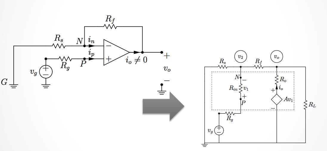
We can simplify the model of the op-amp so that we can solve for the output voltage as a function of the input voltage.
October 26th 2015
Continuing Non-Inverting Amplifiers
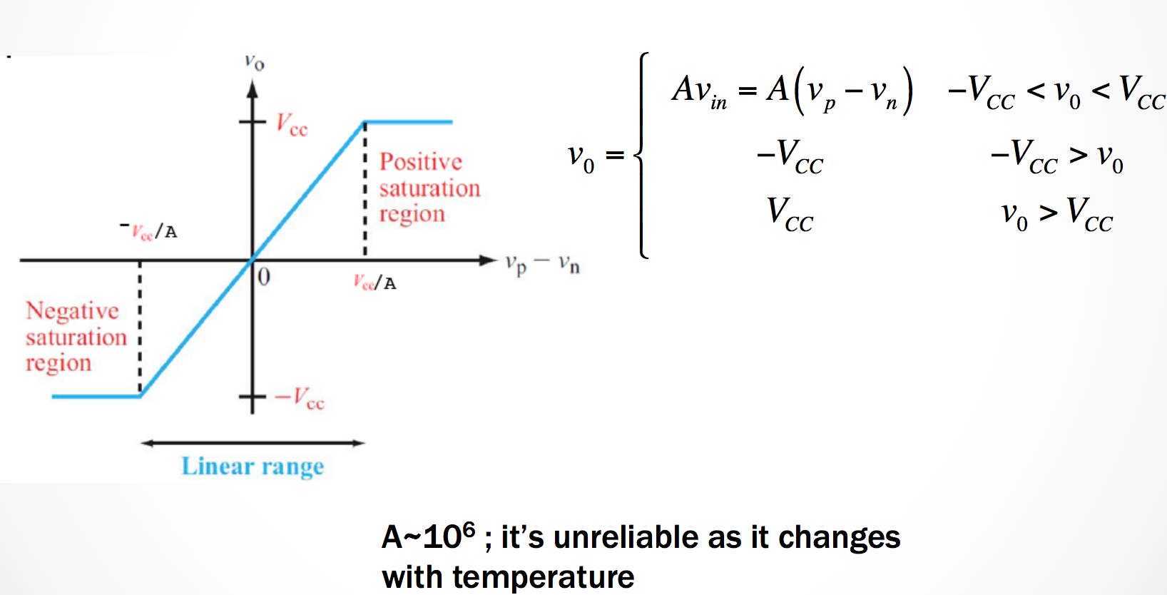
In short: The voltage output from an operational amplifier will stay between the two input voltages of \(-V_{cc}\) and \(+V_{cc}\).
The slope of the range then depends on our Amplifier’s gain, \(V_{cc}/A\).
- If an op-amp- is not saturated we can analyze any circuit having an op-amp by replacing it by its equivalent circuit.
\[V_o = \frac{A}{1 + FA}\]
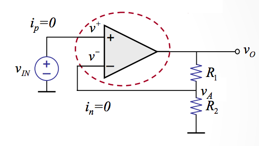
\[V_o = ( 1 + \frac{R_1}{R_2})V_{IN}\]
Inverting Operational Amplifiers
Now we’re going to take a look at inverting amplifiers
From this we focus on the 4 different types of amplifier circuits. The 4 types we focus on are:
- Inverting
- Non-Inverting
- Summing
- Difference
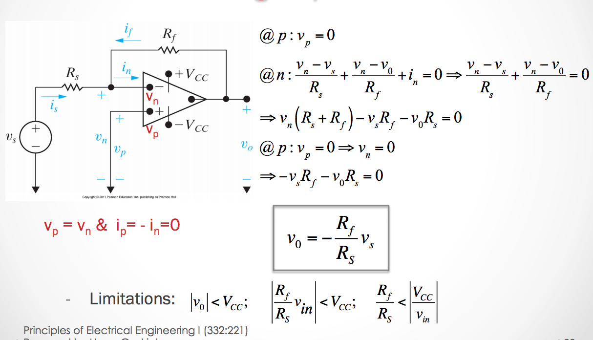
Inverting Op Amp Circuit
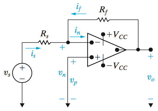
In an inverting amplifier our gain values \(K\) will be negative because we want the output to be the inverted from the input.
The output voltage is calculated as:
\[v_0 = \frac{-R_f}{R_s}v_s\]
It might also be useful to note that
- \[i_s = \frac{v_s}{R_s}\]
- \[i_f = \frac{v_0}{R_f}\]
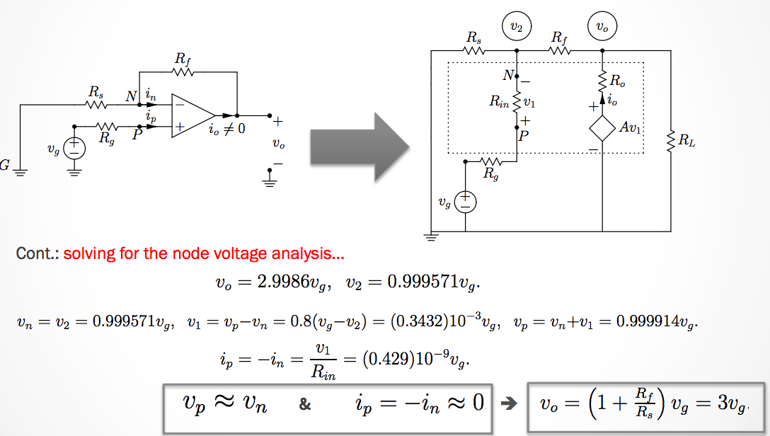
Non-Inverting Op Amp Circuit
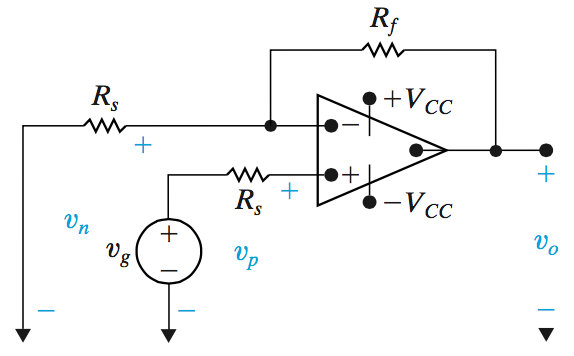
In an inverting amplifier our gain values \(K\) will not be negative because we want the output to be the same sign as the input.
The output voltage is calculated as:
\[v_0 = \frac{R_f + R_s}{R_s}v_g\]
Operation in the linear range requires that:
\[\frac{R_s + R_f}{R_s} < \left|\frac{V_{CC}}{v_g}\right|\]
Summing Op Amp Circuit
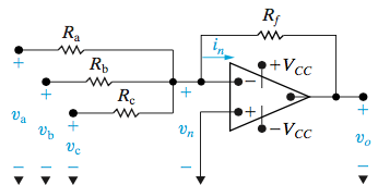
In a summing amplifier circuit, the output voltage can be related by:
\[v_0 = -(\frac{R_f}{R_a}v_a + \frac{R_f}{R_b}v_b + \frac{R_f}{R_c}v_c)\]
Now if \(R_s = R_a = R_b = R_c\) (all resistors equal) then we can say the output voltage is
- \[v_0 = -\frac{R_f}{R_s}(v_a + v_b + v_c)\]
Then if we find that \(R_s = R_f\), the summing amplifier’s output is simply
- \[v_0 = -(v_a + v_b + v_c)\]
Difference Op Amp Circuit
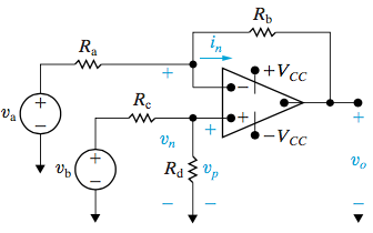
Difference amplifier circuits are slighly different from the previous ones. However we can still simplify the equation to obtain our output voltage. We say for the difference circuit that
\[v_0 = \frac{R_d(R_a + R_b)}{R_a(R_c + R_d)}v_b - \frac{R_b}{R_a}v_a\]
But then if we find that the circuit variables satisfies the equation: \(\frac{R_a}{R_b} = \frac{R_c}{R_d}\), then we can represent this as
\[v_0 = \frac{R_b}{R_s}(v_b - v_a)\]
November 2nd 2015
Unit 6 - Inductance and Capacitance
Up until now we assumed that everything in a circuit happened instantaneously.
capacitors and inductors have inputs and outputs that depends on time!
These elements store energy at different times and they may either produce or absorb energy.
Capacitors and Inductors
Capacitors and Inductors: Energy Storage
- Capacitors store energy in an electric field
- Inductors store energy in a magnetic field
- Capacitors and inductors are passive dynamic elements
- Can store energy supplied by a circuit
- Can return stored energy to a circuit
- Cannot supply more energy to a circuit than it has stored.
Capacitance
Capacitance is a measure of the ability of a device to store energy in the form of a separated charge or an electric field
- The strength of capacitors is measured in Farads
- Capacitance is represented by the letter C
- Typical capacitors are measured from pico-farads (\(pF\)) to micro-farads (\(\mu F\)).
\[C = \frac{\epsilon A}{d}\]
\[q = C \cdot v(t)\]
It should be noted that if there is no change in voltage, current DOES NOT flow through a capacitor.
Capacitor - Current, Charge, Power, and Energy
We can calculate the energy stored in a capacitor over time using the following formulas:
- \[i(t) = C \frac{d}{dt}(v(t))\]
- \[C = \frac{q(t)}{v(t)}\]
- \[v(t) = \frac{q(t)}{C}\]
So then using the integration from \(t_0\) to \(t\) for charge, then we can find the work required which we find as
\[W = \frac{1}{2}Cv^2(t) = \frac{1}{2}\frac{q^2(t)}{C} = \frac{1}{2}q(t)v(t)\]
Finding the Voltage and Current from a graph of capacitor states.
We can find the graph for voltage or current for a capacitor given that we have at least one of the graphs.
- We know that the graph for current in a capacitor is the derivative of the voltage graph
- That is the voltage graph is the integral of the current graph.
We can also solve for the total charge on a place capacitor knowing that \(v(t) = \frac{q(t)}{C}\)
Energy From a Capacitor over Time
The work from a capacitor is the integral of the power over a period of time.
Simplifying Capacitors
It’s very easy to simplify capacitors. They are similar to resistors in how we simplified them. The only difference is that the way we add them together is flipped.
That is, in parallel
\[C_{eq} = C_1 + C_2 + ... + C_n\]
and in series:
\[\frac{1}{C_{eq}} = \frac{1}{C_1} + \frac{1}{C_2} + ... + \frac{1}{C_n}\]
November 5th 2015
Energy Stored in a Capacitor
\[i(t) = C\frac{dv(t)}{dt}\] \[w = \frac{1}{2}Cv^2(t)\]Inductance
- Inductance is a measure of the ability of a device to store energy in the form of a magnetic field.
- The strength of inductors is measured in Henrys
- Inductance is usually represented by the letter L
- L values typically range from \(1\mu H\) to \(10 H\).
- The polarity of the voltage is such as to oppose the change in current (Lenz’s Law).
To calculate the inductance of a inductor we can use the following equation:
\[L = \frac{\mu N^2A}{l}\]
And the voltage from an inductor
\[v(t) = L\frac{di(t)}{dt}\]
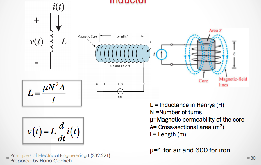
The factors that affect inductance:
- N: The number of turns in a capacitor. The more turns we have then the coil will generate a greater magnetic force - N is usually measured in \(\frac{Amps}{turns}\)
- \(\mu\): The magnetic permeability of the core of the inductor.
- A: The cross sectional area (\(m^2\)) of the coil. The greater the coil area, then the less opposition there is to the formation of the magnetic flux for a given amount of force.
-
l: Length (\(m\)): the longer the path for the magnetic field flux, the more opposition to the formation of flux it experiences for any given amount of field force.
- \(\mu=1\) for air, and \(600\) for iron.
The work done by an inductor is proportional to the current flowing through it. We can say that:
\[w(t) = \frac{1}{2}Li^2(t)\]
Inductors in Series and in Parallel
Inductors simplify similar to resistors.
In Series
\[L_{eq} = L_1 + L_2 + L_3 + ... + L_n\]
In Parallel:
\[\frac{1}{L_{eq}} = \frac{1}{L_1} + \frac{1}{L_2} + \frac{1}{L_3} + ... + \frac{1}{L_n}\]
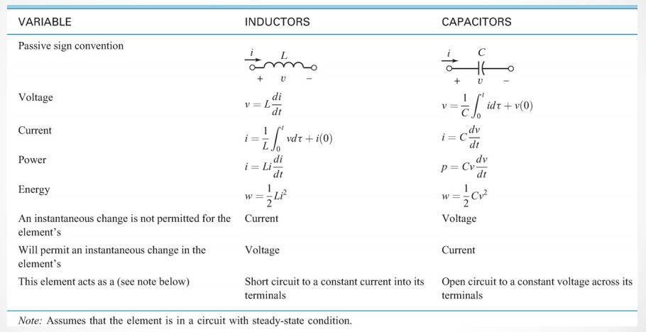
Initial Conditions of DC Switched Circuits
- A circuit at steady state means that the switches in the circuit have been in the same position for a long period of time.
- If all independent voltage and current sources are DC and the circuits are in steady state, then all of the element currents and voltages are also constant (with respect to time)
If a DC circuit is steady state then,
- An inductor behaves as a short circuit
- A capacitor in the circuit behaves as an open circuit
November 9th 2015
Unit 9: DC & Sinusoidal Transient and Steady State Response Phasor (frequency) Domain Analysis
A Sinusoidal Signal - AC (Alternating Current)
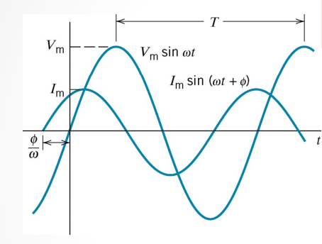
In AC current the voltage level alternates with respect to a trigonometric sine function. The general equation is
\[v(t) = V_mcos(\omega t + \phi)\]
And our variables:
- \(\omega = 2\pi f\) the angular frequency in radians/second.
- \(f = \frac{1}{T}\) is the frequency measured in Hertz.
- \(T = \frac{1}{f}\) is the period in seconds.
- \(\phi\) is the angle shift in radians (also occassionally expressed in degrees).
So when our voltage shifts up and down, we also find that we have a current alternating as well.
However sometimes these are not always in phase, that is the peaks and troughs of each function will not line up perfectly.
So we can say that if voltage is lagging then the current is going to be leading.
Or conversely, if the voltage reaches its peak before the current does, we say the voltage leads and that the current lags.
Charging a Capacitor from a DC source through a Resistance
We can analyze the circuit using KVL.
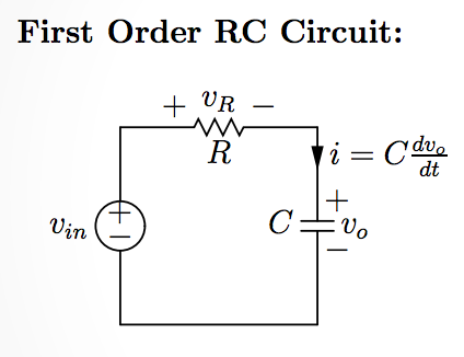
- \[-V_{in} + v_R + v_0 = 0\]
- \[v_R = i_RR\]
- \[i_R = i_C = C\frac{dv_0}{dt} => v_R = RC\frac{dv_0}{dt}\]
- \[-V_{in} + RC\frac{dv_0}{dt} + v_0 = 0\]
- \[V_{in} = RC\frac{dv_0}{dt} + v_0\]
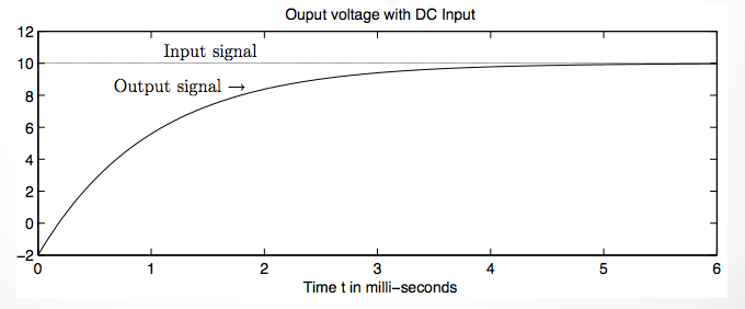
From this we have a first order differential equation. Generally this equation shouldn’t be too difficult to solve.
After solving this differential equation for \(v_0\) we find that
\[v_0(t) = (v_0(0) - E)e^{\frac{-t}{RC}} + E\]
- The part of the equation with \((v_0(0) - E)e^{\frac{-t}{RC}}\) is called the transient response for the circuit.
- The second part \(+ E\) is what we call the steady state response of the circuit.
Capacitor Charging for an AC Source
So now what happens if our source \(V_{in}\) is an AC source where the function of the output is \(Acos(\omega t)\)?
After quite a longer derivation we find that
\[v_o(t) = (v_o(0) - \frac{A}{1 + \omega^2R^2C^2})e^{\frac{-t}{RC}} + \frac{A}{1 + \omega^2R^2C^2}(cos(\omega t) + \omega RCsin(\omega t))\]
So what can we tell from this equation?
For a sinusoidal input voltage, the steady state output voltage is a sinusoidal signal of the same angular frquency \(\omega\) but could have **different ampligtude and phase angle.
Currents will also be sinusoidal signals with the same angular frequency \(\omega\) and a different amplitude and phase angles.
If we simplify the analysis by using only the amplitude and phase information we get Phasor Domain Analysis
- Euler’s Formula: \(e^{jx} = cos(x) + jsin(x)\)
- \(Ae^{j(\omega t + \theta_1)} = Ae^{j\omega t}e^{j\theta}\).
- We call\(\frac{A_1}{\theta_1}\) the phasor of \(A_1cos(\omega t + \theta_1)\)q
- We call\(\frac{A_2}{\theta_2}\) the phasor of \(A_2cos(\omega t + \theta_2)\)
- And in general, We call \(\frac{A}{\theta}\) the phasor of \(Acos(\omega t + \theta)\)
When we use \(cos(\omega t)\) as the reference sinusoid, we have the following transformation from the time domain to phasor domain:
\[Acos(\omega t + \theta) ==> Ae^{j\theta} = \frac{A}{\theta}\]
When we use \(cos(\omega t)\) as the reference sinusoid, we have the following inverse tranformation from phasor domain to time domain.
November 12th 2015
Complex Numbers
A complex number is in the form
\[a + jb\]
The simples complex value is \(i = j = \sqrt{-1}\)
Recall Euler’s Formula is
\[e^{jx} = cos(x) + jsinx\]
Where \(a = cos(x)\) and \(b = sin(x)\).
\(a\) and \(b\) are both real numbers.
- \(a\) is for the real part of the number.
- \(b\) is for the imaginary part of the number.
Plotting Imaginary Numbers
Imagine our axes in a 2-dimensional graph. Normally in 2D we define the horizontal axis as the x axis, and the vertical axis as the y-axis.
However in dealing with imaginary numbers we change the axes slightly.
When plotting imaginary numbers:
- The horizontal axis is the real axis.
- The vertical axis is the imaginary axis.
What about on a polar coordinate system?
We can simply represent \(a + jb\) as
\[a + jb = M(cos(\theta) + jsin(\theta))\]
This allows us to express the complex numbers in a polar coordinate system on a graph as well.
So now we have two ways of writing complex numbers
- \[a + jb\]
- \[M(cos(\theta) + jsin(\theta))\]
But wait!
Do you remember the Euler formula from earlier?
We can manipulate the 2 representation above to actually make our 3rd representation
\[Me^{j\theta}\]
Converting from Rectangular to Polar Coordinates
So we can convert from rectangular coordinates to polar by simply using the relationships:
- \[tan(\theta) = \frac{y}{x}\]
- \[M = \left|z\right| = \sqrt{x^2+y^2}\]
- \[x = Mcos(\theta)\]
- \[y = Msin(\theta)\]
Adding and Subtracting Complex Numbers
When adding or subtracting these types of numbers, we simply only add or subtract only the real parts to obtain the sum or difference of real answers. Then we we simply add or subtract all imaginary parts to obtain the sum or difference of imaginary parts.
For example, given the following:
\[(a + jb) + (c + jd)\]The result is
\[(a+c) + j(b + d)\]But what happens if we have items in polar coordinates?
Well, the simplest solution is to actually just convert the numbers to rectangular
Multiplication of Complex Numbers
Given the numbers:
- \[a + jb\]
- \[c + jd\]
Then the multiplication result of these two is
\[ac + jad + jbc + j^2bd\]Simplified this yields
\[(ac - bd) + j(ad + bc)\]We subtract \(bd\) because when we have \(j^2\), we find it is equal to \(-1\) given the definition of \(j\)
For polar coordinates:
\[M_1M_2e^{j(\theta_1+\theta_2)} = M_1M_2, \theta_1+\theta_2\]Complex Conjugate
The complex conjugate of a number \(z = a + jb\), we find that the complex conjugate denoted \(z^*\), we find is equal to
\[z = a + jb, z^* = a - bj\]
Properties of Complex Conjugates
If we multiply two complex conjugates together, we find that in the expansion:
\[a^2 + jab - jab -j^2b\]
which is equal to the square magnitude:
\[a^2 + b^2\]
Division of Complex Numbers
The division of complex number using the rectangular coordinate system is difficult and requires a fair amount of algebra. However, converted to polar coordinates it is much easier
\[\frac{M_1e^{j\theta_1}}{M_2e^{j\theta_2}} = M_1M_2, \theta_1-\theta_2\]
November 19th 2015
Conversions from the Time Domain to Phasor Domain
Conversions from the time domain to a phasor domain make our evaluations and analysis of AC response circuits much easier.
For every item in the time domain, we have an equivalent in the phasor domain. Remember that \(j=\sqrt{-1}\).
For a general overview of the Time-Domain to Phasor-Domain conversions see the table below.
| Time Domain | Phasor (Frequency) Domain |
|---|---|
| \(f(t)=Acos(\omega t + \theta)\) | \(Ae^{j\theta}=A\angle\theta\) |
| \(v(t)=V_mcos(\omega t+\theta_v)\) | \(V=V_me^{j\theta_v}=V_m\angle\theta_v\) |
| \(i(t)=I_mcos(\omega t+\theta_i)\) | \(I=I_me^{j\theta_i}=I_m\angle\theta_i\) |
| \(v_\Delta (t)=\frac{dv(t)}{dt}=V_m\omega cos(\omega +\theta_v +90)\) | \(V_\Delta = j\omega V\) |
| \(v_{\int}(t)=\int v(t) = \frac{V_m}{\omega}cos(\omega t+\theta_v -90)\) | \(V_{\int}=\frac{1}{j\omega}V\) |
Now when dealing with RC and RLC circuits we normally would calculate the voltage/current/resistance by using Ohm’s law (\(V=IR\)). When dealing with phasors our calculations are simplified.
Resistance
Because our voltage is a function of time we need to deal with functions when we calculate our values. But in the phasor domain it is simply V=IR (When \(V\) and \(I\) are in phase!!).
Time Domain: \(i(t)R = v(t)\)
Phasor Domain: \(\frac{V}{I} = R\)
Inductance
Time Domain: \(L\frac{di(t)}{dt}=v(t)\)
Phasor Domain: \(\frac{V}{I} = j\omega L\)
Capacitance
Time Domain: \(C\frac{dv(t)}{dt}=i(t)\)
Phasor Domain: \(\frac{V}{I} = -j\frac{1}{\omega C}\)
Impedance
Impedance is in the units of Ohms.
- \(R\) is the real part of the impedance (resistance)
- \(X\) is the imaginary part of impedance (reactance)
\[Z = \frac{V}{I} = R + jX\]
Admittance
Admittance is in the units of Siemens (\(\frac{1}{\Omega})\).
- \(G\) is the real part of the admittance (conductance)
- \(B\) is the imaginary part of admittance (susceptance)
\[Y = \frac{1}{Z} = \frac{I}{V} = G + jB\]
RLC in Time vs Phasor
| Time Domain | Phasor Domain |
|---|---|
| Resistance \(R\) | Impedance \(Z=R\) |
| Inductance \(L\) | Impedance \(Z=j\omega L\) |
| Capacitance \(C\) | Impedance \(Z=-j\frac{1}{\omega C}\) |
November 23rd 2015
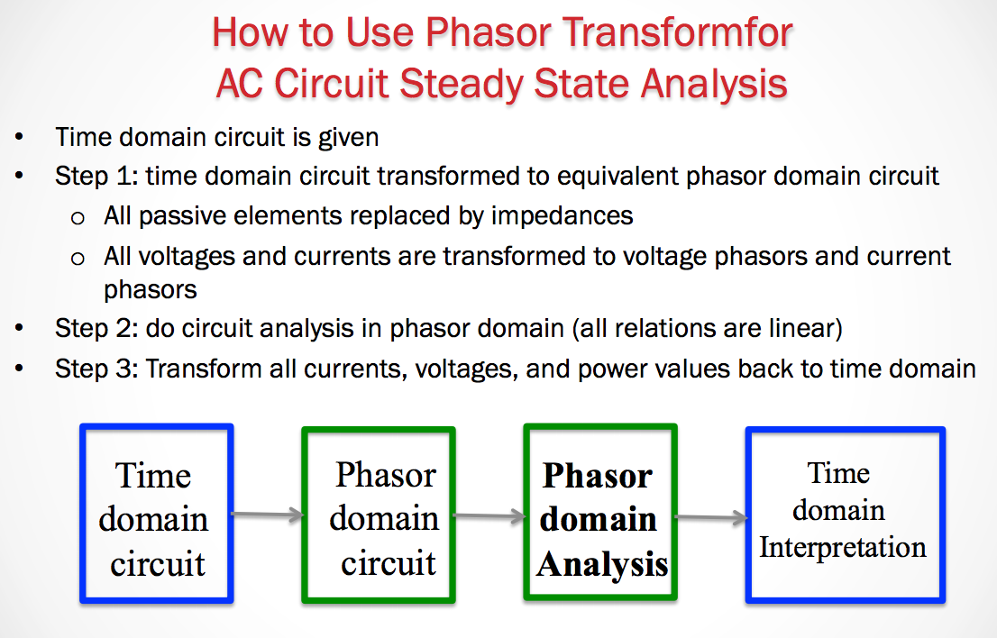
In solving these circuits we need to first move from the time domain to the phasor domain before analyzing the circuit. After which we then analyze the circuit, and then finally convert back to the time domain
Maximum Power Transfer
This occurs when the \(Z_{load} = Z_{TH}\).
November 30th 2015
Analyzing AC Circuits in the Phasor Domain
When analyzing circuits in the phasor domain we need to convert all of the elements in the circuit to have impedance values for the phasor domain.
Remember Impedances are in the units of Ohms (\(\Omega\)).
Also remember that to convert different elements to the phasor domain they each have their own respective equations.
- Resistor: \(Z=R\)
- Capacitor: \(Z = j\omega L\)
- Inductor: \(Z = -j\frac{1}{\omega C}\)
After converting all elements to the phasor domain we can then solve for our circuit using node voltage or mesh current method using the impedances for each.
However you must keep imaginary and real values separated. Remember that the value \(j\) represents \(\sqrt{-1}\). So we cannot simply add the impedance values from resistors and then capacitors (or inductors) because we must separate the real and imaginary values.
This means that it is possible for solutions (voltage, current) to a circuit to be in terms of a real and imaginary values when solving for the entire circuit in the phasor domain.
How is that possible?
Remember that we’re dealing in the phasor domain because we have an AC current/voltage source. The equation that represents the source has the form \(V(t) = Acos(\omega t + \phi)\).
If we recall from earlier we represented our complex terms as a real portion and an angle.
The imaginary part of a solution will represent the tangent value of the angle, \(\phi\). Then the real part will represent the amplitude, \(A\).
December 3rd 2015
Chapter 10a - Power and Phasor Domain Analysis
The root mean square (RMS) value of a periodic function \(x(t)\) is defined as:
\[X_{rms} = \sqrt{\frac{1}{T}\int^{t_o+T}_{t_o} x^2(\tau)d\tau}\]
This RMS value is equivalent to the **maximum (peak) voltage divided by \(\sqrt{2}\).
\[V_{rms} = \frac{V_m}{\sqrt{2}}\]
The same thing applies for the current in AC circuits.
\[I_{rms} = \frac{I_m}{\sqrt{2}}\]
The rms value of any periodic voltage or current delivers the same average power to a resistor as a DC voltage with the same value.
- rms values allow us to compare the effect of various periodic voltages to the effect of a DC voltage, also alled effective values.
So for the average power delivered to a circuit, we find that given a simple AC source with function \(V_mcos(\omega t + \theta_v)\), then the average power delivered to the resistor is:
\[P_{avg} = \frac{V_{rms}^2}{R}\]
So then we know how to calculate our power in the time domain…but what about the phasor domain?
The instantaneous power in an AC system in the time domain is
\[P = -\frac{V_mI_m}{2}sin(\theta_v-\theta_i)sin(2\omega t)\]
Relation between voltage and Current on Capacitors and Inductors
ELI the ICE man
This can help us rememebr when voltage lags or leads in a capacitor and how we can estimate the phase angles.
- ELI - Voltage LEADS current in an inductor by \(90^o\).
- ICE - Voltage LAGS current in a capacitor by \(90^o\).
Another way that you could remember this is that capacitors have a negative imaginary impedance value. Because it is negative, this corresponds to a -90 degrees - LAG.
We can also say the same for inductors where inductors have a positive imaginary impedance value, so this positive imaginary value corresponds to a +90 degree phase - LEAD.